- Basic Semiconductor Physics and Technology (here for sample of version requiring registration)
- The pn Junction (here for sample of version requiring registration)
- Power Switching Devices and their Static Electrical Characteristics (here for sample of version requiring registration)
- Electrical Ratings and Characteristics of Power Semiconductor Switching Devices (here for sample of version requiring registration)
- Cooling of Power Switching Semiconductor Devices (here for sample of version requiring registration)
- Load, Switch, and Commutation Considerations (here for sample of version requiring registration)
- Driving Transistors and Thyristors (here for sample of version requiring registration)
- Protecting Diodes, Transistors, and Thyristors (here for sample of version requiring registration)
- Switching-aid Circuits with Energy Recovery (here for sample of version requiring registration)
- Series and Parallel Device Operation and Protection (here for sample of version requiring registration)
- Naturally Commutating Converters (here for sample of version requiring registration)
- AC Voltage Regulators (here for sample of version requiring registration)
- DC Choppers (here for sample of version requiring registration)
- Power Inverters (here for sample of version requiring registration)
- Switched-mode and Resonant dc Power Supplies (here for sample of version requiring registration)
- Capacitors
- Soft Magnetic Materials
- Resistors
Multiplexer


In electronics, a multiplexer or mux is a device that selects one of several analog or digital input signals and forwards the selected input into a single line. A multiplexer of 2n inputs has n select lines, which are used to select which input line to send to the output.
In [Digital Logic], a "Multiplexer" converts multiple input to a single output.
An electronic multiplexer makes it possible for several signals to share one device or resource, for example one A/D converter or one communication line, instead of having one device per input signal.
On the other end, a demultiplexer (or demux) is a device taking a single input signal and selecting one of many data-output-lines, which is connected to the single input. A multiplexer is often used with a complementary demultiplexer on the receiving end.
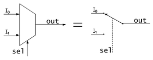
An electronic multiplexer can be considered as a multiple-input, single-output switch, and a demultiplexer as a single-input, multiple-output switch. The schematic symbol for a multiplexer is an isosceles trapezoid with the longer parallel side containing the input pins and the short parallel side containing the output pin. The schematic on the right shows a 2-to-1 multiplexer on the left and an equivalent switch on the right. The sel wire connects the desired input to the output.
Contents
[hide]- 1 Telecommunications
- 2 Cost savings
- 3 Digital multiplexers
- 3.1 Chaining multiplexers
- 3.2 List of ICs which provide multiplexing
- 4 Digital demultiplexers
- 4.1 List of ICs which provide demultiplexing
- 5 Multiplexers as PLDs
- 6 See also
- 7 References
- 8 Further reading
بقیه و متن کامل در ادامه مطالب...
Transistor–transistor logic

Transistor–transistor logic (TTL) is a class of digital circuits built from bipolar junction transistors (BJT) and resistors. It is called transistor–transistor logic because both the logic gating function (e.g., AND) and the amplifying function are performed by transistors (contrast this with RTL and DTL).
TTL is notable for being a widespread integrated circuit (IC) family used in many applications such as computers, industrial controls, test equipment and instrumentation, consumer electronics, synthesizers, etc. The designation TTL is sometimes used to mean TTL-compatible logic levels, even when not associated directly with TTL integrated circuits, for example as a label on the inputs and outputs of electronic instruments.[1]
Contents
[hide]- 1 History
- 2 Implementation
- 2.1 Fundamental TTL gate
- 2.2 TTL with a "totem-pole" output stage
- 3 Interfacing considerations
- 4 Packaging
- 5 Comparison with other logic families
- 6 Sub-types
- 7 Applications
- 7.1 Analog applications
- 8 See also
- 9 Notes
- 10 References
- 11 External links
بقیه و متن کامل مقاله در ادامه مطالب....
CMOS

Complementary metal–oxide–semiconductor (CMOS) (![]() /ˈsiːmɒs/) is a technology for constructing integrated circuits. CMOS technology is used in microprocessors, microcontrollers, static RAM, and other digital logic circuits. CMOS technology is also used for several analog circuits such as image sensors, data converters, and highly integrated transceivers for many types of communication. Frank Wanlass patented CMOS in 1967 (US patent 3,356,858).
/ˈsiːmɒs/) is a technology for constructing integrated circuits. CMOS technology is used in microprocessors, microcontrollers, static RAM, and other digital logic circuits. CMOS technology is also used for several analog circuits such as image sensors, data converters, and highly integrated transceivers for many types of communication. Frank Wanlass patented CMOS in 1967 (US patent 3,356,858).
CMOS is also sometimes referred to as complementary-symmetry metal–oxide–semiconductor (or COS-MOS[1]). The words "complementary-symmetry" refer to the fact that the typical digital design style with CMOS uses complementary and symmetrical pairs of p-type and n-type metal oxide semiconductor field effect transistors (MOSFETs) for logic functions.
Two important characteristics of CMOS devices are high noise immunity and low static power consumption. Significant power is only drawn when the transistors in the CMOS device are switching between on and off states. Consequently, CMOS devices do not produce as much waste heat as other forms of logic, for example transistor-transistor logic (TTL) or NMOS logic. CMOS also allows a high density of logic functions on a chip. It was primarily for this reason that CMOS became the most used technology to be implemented in VLSI chips.
The phrase "metal–oxide–semiconductor" is a reference to the physical structure of certain field-effect transistors, having a metal gate electrode placed on top of an oxide insulator, which in turn is on top of a semiconductor material. Aluminum was once used but now the material is polysilicon. Other metal gates have made a comeback with the advent of high-k dielectric materials in the CMOS process, as announced by IBM and Intel for the 45 nanometer node and beyond.[2]
Contents
[hide]- 1 Technical details
- 2 Composition
- 3 Inversion
- 3.1 Duality
- 3.2 Logic
- 3.3 Example: NAND gate in physical layout
- 4 Power: switching and leakage
- 5 Analog CMOS
- 6 Temperature range
- 7 See also
- 8 References
- 9 Further reading
- 10 External links
بقیه و متن کامل در ادامه مطالب...
Flip-flop (electronics)

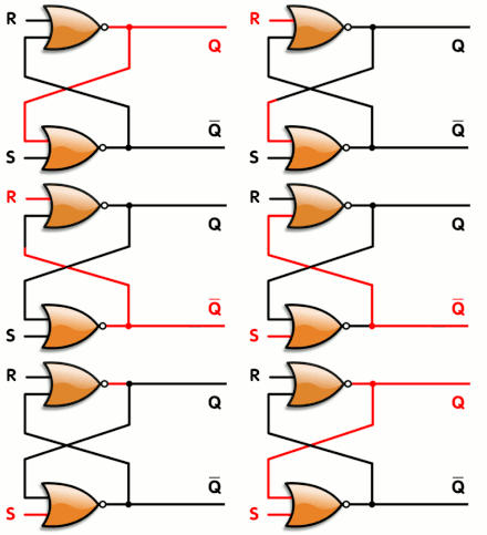
In electronics, a flip-flop or latch is a circuit that has two stable states and can be used to store state information. The circuit can be made to change state by signals applied to one or more control inputs and will have one or two outputs. Flip-flops and latches are a fundamental building block of digital electronics systems used in computers, communications, and many other types of systems.
Flip-flops and latches are used as data storage elements. Such data storage can be used for storage of state, and such a circuit is described as sequential logic. When used in a finite-state machine, the output and next state depend not only on its current input, but also on its current state (and hence, previous inputs.) It can also be used for counting of pulses, and for synchronizing variably-timed input signals to some reference timing signal.
Flip-flops can be either simple (transparent or opaque) or clocked (synchronous or edge-triggered); the simple ones are commonly called latches.[1] The word latch is mainly used for storage elements, while clocked devices are described as flip-flops.[2]
Contents
[hide]- 1 History
- 2 Implementation
- 3 Flip-flop types
- 3.1 Simple set-reset latches
- 3.1.1 SR NOR latch
- 3.1.2 SR NAND latch
- 3.1.3 JK latch
- 3.2 Gated latches and conditional transparency
- 3.2.1 Gated SR latch
- 3.2.2 Gated D latch
- 3.2.3 Earle latch
- 3.3 D flip-flop
- 3.3.1 Classical positive-edge-triggered D flip-flop
- 3.3.2 Master–slave pulse-triggered D flip-flop
- 3.3.3 Edge-triggered dynamic D flip-flop
- 3.4 T flip-flop
- 3.5 JK flip-flop
- 3.1 Simple set-reset latches
- 4 Metastability
- 5 Timing considerations
- 5.1 Setup and hold times
- 5.2 Propagation delay
- 6 Generalizations
- 7 See also
- 8 References
بقیه و متن کامل مقاله در ادامه مطالب...
MOSFET


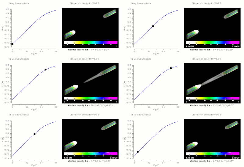
The metal–oxide–semiconductor field-effect transistor (MOSFET, MOS-FET, or MOS FET) is a transistor used for amplifying or switching electronic signals. The basic principle of this kind of transistor was first proposed by Julius Edgar Lilienfeld in 1925. In MOSFETs, a voltage on the oxide-insulated gate electrode can induce a conducting channel between the two other contacts called source and drain. The channel can be of n-type or p-type (see article on semiconductor devices), and is accordingly called an nMOSFET or a pMOSFET (also commonly nMOS, pMOS). It is by far the most common transistor in both digital and analog circuits, though the bipolar junction transistor was at one time much more common.
The 'metal' in the name is now often a misnomer because the previously metal gate material is now often a layer of polysilicon (polycrystalline silicon). Aluminium had been the gate material until the mid 1970s, when polysilicon became dominant, due to its capability to form self-aligned gates. Metallic gates are regaining popularity, since it is difficult to increase the speed of operation of transistors without metal gates.
IGFET is a related term meaning insulated-gate field-effect transistor, and is almost synonymous with MOSFET, though it can refer to FETs with a gate insulator that is not oxide. Another synonym is MISFET for metal–insulator–semiconductor FET.
Contents
- 1 Composition
- 2 Circuit symbols
- 3 MOSFET operation
- 3.1 Metal–oxide–semiconductor structure
- 3.2 MOSFET structure and channel formation
- 3.3 Modes of operation
- 3.4 Body effect
- 4 History
- 5 CMOS circuits
- 5.1 Digital
- 5.2 Analog
- 6 MOSFET scaling
- 6.1 Reasons for MOSFET scaling
- 6.2 Difficulties arising due to MOSFET size reduction
- 6.2.1 Higher subthreshold conduction
- 6.2.2 Increased gate-oxide leakage
- 6.2.3 Increased junction leakage
- 6.2.4 Lower output resistance
- 6.2.5 Lower transconductance
- 6.2.6 Interconnect capacitance
- 6.2.7 Heat production
- 6.2.8 Process variations
- 6.2.9 Modeling challenges
- 7 MOSFET construction
- 7.1 Gate material
- 7.2 Insulator
- 7.3 Junction design
- 8 Other MOSFET types
- 8.1 Dual gate MOSFET
- 8.1.1 FinFET
- 8.2 Depletion-mode MOSFETs
- 8.3 NMOS logic
- 8.4 Power MOSFET
- 8.5 DMOS
- 8.6 RHBD MOSFETs
- 8.1 Dual gate MOSFET
- 9 MOSFET analog switch
- 9.1 Single-type MOSFET switch
- 9.2 Dual-type (CMOS) MOSFET switch
- 10 References and notes
- 11 See also
- 12 External links
بقیه و متن کامل مقاله در ادامه مطالب...
Logic gate
A logic gate is an idealized or physical device implementing a Boolean function, that is, it performs a logical operation on one or more logic inputs and produces a single logic output. Depending on the context, the term may refer to an ideal logic gate, one that has for instance zero rise time and unlimited fan-out, or it may refer to a non-ideal physical device.[1] (see Ideal and real op-amps for comparison)
Logic gates are primarily implemented electronically using diodes or transistors, but can also be constructed using electromagnetic relays (relay logic), fluidic logic, pneumatic logic, optics, molecules, or even mechanical elements. With amplification, logic gates can be cascaded in the same way that Boolean functions can be composed, allowing the construction of a physical model of all of Boolean logic, and therefore, all of the algorithms and mathematics that can be described with Boolean logic.
Contents
[hide]- 1 Background
- 2 Logic gates
- 3 Symbols
- 4 Universal logic gates
- 5 De Morgan equivalent symbols
- 6 Data storage
- 7 Three-state logic gates
- 8 Miscellaneous
- 9 History and development
- 10 Implementations
- 11 See also
- 12 References
- 13 Further reading
- 14 External links
بقیه و متن کامل مقاله در ادامه مطالب...
Integrated circuit


An integrated circuit or monolithic integrated circuit (also referred to as IC, chip, and microchip) is an electronic circuit manufactured by diffusion of trace elements into the surface of a thin substrate of semiconductor material.
Integrated circuits are used in virtually all electronic equipment today and have revolutionized the world of electronics. Computers, cellular phones, and other digital appliances are now inextricable parts of the structure of modern societies, made possible by the low cost of production of integrated circuits.
Contents
[hide]- 1 Introduction
- 2 Terminology
- 3 Invention
- 4 Generations
- 4.1 SSI, MSI and LSI
- 4.2 VLSI
- 4.3 ULSI, WSI, SOC and 3D-IC
- 5 Advances in integrated circuits
- 6 Classification
- 7 Manufacturing
- 7.1 Fabrication
- 7.2 Packaging
- 7.3 Chip labeling and manufacture date
- 8 Legal protection of semiconductor chip layouts
- 9 Other developments
- 10 Silicon labelling and graffiti
- 11 Notable ICs and IC families
- 12 See also
- 13 References
- 14 Further reading
- 15 External links
بقیه و متن کامل مقاله در ادامه مطالب....
صفحه قبل 1 صفحه بعد


